Simpson 3100 PSI Pressure Washer Manual: Article Plan
This comprehensive guide details the Simpson 3100 PSI pressure washer, covering model MS60763-S and variations. It provides instructions, safety precautions, and troubleshooting steps for optimal performance.
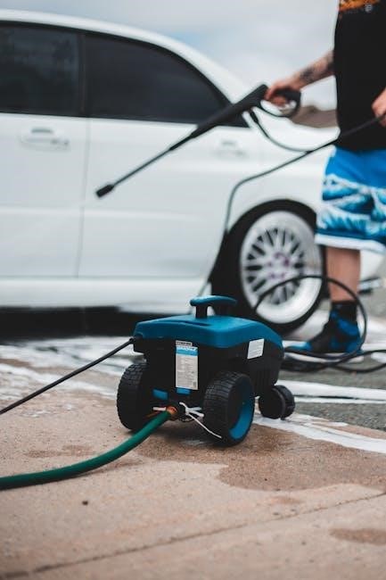
The Simpson 3100 PSI pressure washer is a powerful cleaning tool designed for residential use. This model, including the MS60763-S, delivers 3100 PSI at 2.4 GPM, effectively tackling various outdoor cleaning tasks. It’s ideal for decks, patios, and vehicles, offering a balance of performance and affordability.
This manual provides essential information for safe and efficient operation, maintenance, and troubleshooting, ensuring a long lifespan for your pressure washer;
Model Numbers and Variations
The core model discussed is the MS60763-S, a 3100 PSI, 2.4 GPM gas-powered pressure washer. However, variations exist within the Simpson MegaShot series. These may include slight differences in accessories or component sourcing, but generally maintain the same performance specifications. Always refer to the specific model number on your unit when ordering parts or contacting customer service for accurate support.
MS60763-S and Related Models
The MS60763-S is a popular residential model, known for its balance of power and affordability. Related models, like the MS61217, share similar specifications – around 3100 PSI and 2.4 GPM – but might feature different pump or engine configurations. Checking the serial number ensures compatibility when sourcing replacement parts or accessing specific troubleshooting guides for your particular unit.
Safety Precautions
Always prioritize safety when operating this pressure washer. Wear safety glasses to protect your eyes from debris. Avoid directing the high-pressure spray at people, animals, or electrical connections. Never modify the pressure washer or use incompatible parts. Ensure proper ventilation when operating the engine, and disconnect the spark plug before maintenance.
General Safety Guidelines
Read the entire manual before using the Simpson 3100 PSI pressure washer. Understand all controls and safety features. Keep children and bystanders away from the operating area. Never leave the machine unattended while running. Wear appropriate clothing, including closed-toe shoes, and avoid loose garments. Inspect the equipment before each use.
High-Pressure Spray Safety
Never point the wand at yourself or others. The high-pressure spray can cause serious injury. Avoid spraying electrical components or outlets. Do not attempt to modify the gun or wand. Always release pressure before disconnecting hoses or nozzles. Be mindful of the spray’s recoil force and maintain a firm grip.
Component Identification
The Simpson 3100 PSI unit features a robust engine, high-pressure pump, and durable spray gun. Key components include various quick-connect nozzles, a high-pressure hose, and a detergent tank. Familiarize yourself with the throttle, choke, and on/off switch locations for safe and efficient operation. Understanding each part is crucial.

Nozzle Selection and Usage
Simpson pressure washers utilize quick-connect nozzles, each delivering a different spray pattern. A 0° nozzle provides a concentrated stream for tough stains, while a 40° nozzle offers a wider fan for general cleaning. Always select the appropriate nozzle for the task to avoid damage. Test in an inconspicuous area first!
Hose and Wand Assembly
Proper hose and wand connection is crucial for safe operation. Ensure the high-pressure hose is securely attached to both the pump and the spray gun. The wand then connects to the spray gun, utilizing a quick-connect mechanism. Verify all connections are tight before starting the engine to prevent leaks and potential injury.
Assembly Instructions
Before initial use, careful assembly is required. This includes attaching the high-pressure hose to the pump outlet, ensuring a secure and leak-proof connection. Next, connect the spray wand to the trigger gun, again verifying a firm fit. Finally, select and attach the desired nozzle to the wand, readying the unit for operation.
Attaching the Hose to the Pump
Securely connect the high-pressure hose to the pump outlet, hand-tightening initially. Then, use a wrench to tighten further, ensuring a watertight seal. Avoid over-tightening, which could damage the fittings. Inspect the connection for any leaks before operation; a loose connection can cause pressure loss and potential injury.

Connecting the Wand and Nozzle
Attach the desired nozzle to the spray wand, ensuring it clicks securely into place. Then, connect the wand to the trigger gun, again verifying a firm connection. Always select the appropriate nozzle for the cleaning task to avoid damage. Never attempt to modify or bypass safety features during nozzle installation.
Operating Instructions
Before starting, ensure all connections are secure and the unit has sufficient oil. Begin by turning on the water supply, then pull the starter cord to ignite the engine. Adjust the throttle for desired pressure, referencing the manual for specific nozzle settings. Always maintain a safe distance from surfaces during operation.
Starting the Engine
Ensure the fuel valve is open and the choke is set to the ‘start’ position. Gently pull the starter cord until resistance is felt, then pull briskly. Repeat if necessary, adjusting the choke as the engine warms. Once running, gradually reduce choke and adjust throttle for optimal performance. Refer to the manual for detailed guidance.
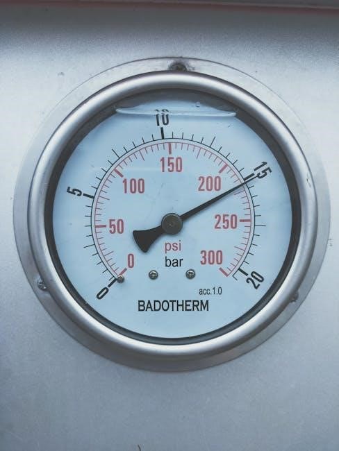
Adjusting Pressure Settings
Utilize the unloader valve to regulate pressure, starting with a lower setting for delicate surfaces. Gradually increase pressure as needed, testing on an inconspicuous area first. Different nozzles also affect pressure; wider nozzles deliver lower pressure. Always prioritize safety and consult the manual for specific nozzle recommendations and pressure guidelines.
Maintenance and Care
Regular maintenance ensures longevity. Clean nozzles after each use to prevent clogging, and inspect the hose for damage. Perform oil changes according to the schedule in the manual – typically after every 50 hours of operation. Store the unit in a dry place, protecting it from freezing temperatures to avoid component damage.
Cleaning the Nozzles

Clogged nozzles reduce performance. Remove nozzles and soak them in a nozzle cleaning solution or white vinegar overnight. Use a small wire or pin to gently clear any remaining debris from the nozzle orifice. Always inspect for wear and replace damaged nozzles promptly to maintain optimal spray patterns and pressure.

Oil Change Procedures
Regular oil changes are crucial for engine longevity. Drain the old oil while the engine is warm, but not hot. Replace the oil filter with a new one, and refill with the recommended oil type (check your manual). Dispose of used oil responsibly at a recycling center. Maintain proper oil levels for peak performance.
Troubleshooting Common Issues
Addressing problems promptly ensures continued operation. If the engine won’t start, check fuel levels, spark plug, and air filter. For pressure loss, inspect the nozzle for clogs, verify hose connections, and ensure adequate water supply. Consult the manual for detailed diagnostics and solutions to common malfunctions.
Engine Won’t Start
A non-starting engine requires systematic checks. First, verify sufficient fuel and a clean air filter. Inspect the spark plug for fouling or damage, replacing if necessary. Ensure the choke is properly positioned. If issues persist, consult the Simpson manual for specific troubleshooting steps related to the engine’s starting mechanism.
Pressure Loss Problems
Reduced pressure often indicates a blockage. Check the nozzle for clogs and clean thoroughly. Inspect the high-pressure hose for kinks or damage, and verify proper connections. A worn pump or faulty unloader valve can also cause pressure loss; consult the Simpson manual for detailed diagnostics and potential repair solutions.
Warranty Information
Simpson offers a warranty on the 3100 PSI pressure washer, covering manufacturing defects. Registration at www.power-washer.us is crucial for validation. Coverage details, including duration and limitations, are outlined in the full manual. Retain your purchase receipt for warranty claims and customer service inquiries.
Registration Process (www.power-washer.us)
Visit www.power-washer.us to register your Simpson 3100 PSI pressure washer. You’ll need the purchase date and serial number, found on the unit. Registration validates your warranty and provides access to replacement parts and service representatives. This ensures efficient support should you encounter any issues with your new pressure washer.
Coverage Details
Simpson’s warranty covers defects in materials and workmanship for a specified period. The duration varies based on the component; refer to the full warranty documentation for specifics. Warranty service requires proof of purchase and registration. Damage from misuse, neglect, or unauthorized repairs is not covered. Contact customer service for claim procedures.
Technical Specifications
The Simpson 3100 PSI pressure washer delivers 3100 pounds per square inch (PSI) with a flow rate of 2.4 gallons per minute (GPM). Engine specifications include a gasoline-powered motor, designed for residential use. Detailed engine displacement and horsepower information can be found within the complete manual.
PSI and GPM Output (3100 PSI, 2.4 GPM)
This Simpson model boasts a powerful 3100 PSI, effectively removing tough dirt and grime. The 2.4 GPM flow rate balances cleaning power with water conservation. These specifications make it ideal for various tasks, including deck cleaning, vehicle washing, and patio restoration, offering efficient performance for homeowners.
Engine Specifications
The Simpson 3100 PSI pressure washer is equipped with a reliable gasoline engine, designed for robust performance. While specific engine details vary, it generally features a straightforward starting system and durable construction. This ensures consistent power delivery for effective cleaning, making it a dependable choice for residential use.
Replacement Parts
Maintaining your Simpson 3100 PSI pressure washer is easy with readily available replacement parts. Commonly replaced components include nozzles, hoses, and filters, ensuring continued optimal performance. Visit www.power-washer.us to locate parts or contact customer service for assistance. Genuine Simpson parts guarantee compatibility and longevity for your cleaning equipment.
Where to Find Replacement Parts
Genuine Simpson replacement parts can be conveniently sourced online at www.power-washer.us. This website offers a comprehensive catalog and easy ordering process. Alternatively, contact Simpson’s Customer Service Department at 1-877-362-4271 for assistance locating specific components. Authorized service centers also stock frequently requested parts for quick repairs.
Commonly Replaced Components
Frequently replaced parts include nozzles, as they wear with use, and the high-pressure hose, susceptible to kinks and damage. The trigger gun and wand are also common replacements. Regularly inspect and replace the oil filter during maintenance. Occasionally, the pump itself may require servicing or complete replacement for continued optimal function.
Customer Support

For assistance with your Simpson 3100 PSI pressure washer, contact their dedicated Customer Service Department at 1-877-362-4271. Extensive online resources, including FAQs and support documentation, are available at www.simpsoncleaning.com. Registering your product at www.power-washer.us streamlines access to parts and service information, ensuring a positive ownership experience.
Contacting Simpson Customer Service (1-877-362-4271)
Reach Simpson’s knowledgeable support team directly by calling 1-877-362-4271. Representatives are available to assist with troubleshooting, parts inquiries, and warranty claims related to your 3100 PSI pressure washer. Be prepared to provide your model number and purchase date for efficient service and resolution of any concerns.
Online Resources (www.simpsoncleaning.com)
Visit www.simpsoncleaning.com for a wealth of support materials for your 3100 PSI pressure washer. Access downloadable manuals, frequently asked questions, replacement parts diagrams, and registration forms for warranty coverage. The website provides comprehensive resources to maximize your cleaning experience and maintain optimal performance.
Frequently Asked Questions (FAQ)
Common questions include troubleshooting starting issues, addressing pressure loss, and identifying appropriate nozzle selections. Users frequently inquire about oil change intervals and winterization procedures. The FAQ section also covers warranty registration and locating nearby service centers for assistance with your Simpson 3100 PSI model.
Additional Resources

For detailed information, consult the Simpson Premium Pressure Washer Instruction Manual. Explore online resources at www.simpsoncleaning.com and www.power-washer.us for warranty registration, replacement parts, and service representative support. These platforms offer expanded guidance beyond this quick-start guide.
Simpson Premium Pressure Washer Instruction Manual (Detailed Information)
The full Simpson manual provides exhaustive details on operation, maintenance, and safety. It covers all aspects, from initial setup and nozzle selection to troubleshooting complex issues. Accessing this resource ensures a thorough understanding of your 3100 PSI pressure washer, maximizing its lifespan and performance.